


If you’ve ever worked in metal stamping, you know there’s nothing more frustrating than a run of stamped parts that are supposed to be identical, but end up with weird size inconsistencies, off-angle bends, or holes that don’t line up with the tooling. As someone who’s been on the supply side of Gap frame crank presses (you might also hear these called C-frame crank presses, which is basically the same thing for our purposes), I get asked all the time: why do even top-of-the-line stamped parts sometimes miss the mark? After troubleshooting with hundreds of stamping shops over the last decade, I’ve seen every possible culprit, and a lot of them tie back directly to how the press itself operates—plus a few small mistakes that are easy to brush off until they start ruining parts.
Let’s start with the press itself, because that’s the foundation of every stamping job. Not all C-frame presses are created equal, and picking the wrong one for your part will tank accuracy before you even run the first piece. For example, if you’re stamping large parts that need tooling extending way out to the side, a standard C-frame might not give you enough clearance, but a deep throat model would work—wait, that’s actually a good example: if you grab a standard single crank C-frame press (check that out here: C-Frame Single Crank Press) for a deep-drawn part that needs extra reach, the frame will flex under load, and that flex translates directly to parts that are slightly shorter or have walls that lean. Same goes for going too small on the press tonnage: if your part needs 50 tons of force and you run it on a 30-ton press, you’re not just risking press damage—you’re not applying enough consistent force to fully form the part, leading to inconsistent dimensions every cycle.
Crank design is another big one. Double crank vs single crank presses— I’ve noticed a lot of new shop owners mix these up. A single crank press is simpler, cheaper, great for smaller, shallower parts, but it has a tiny bit of “wobble” as the crank rotates, especially at the bottom of the stroke. For parts that need tight tolerances (like automotive brackets or electronic housings), that 0.001 inch of wobble might not sound like much, but it adds up over 1,000 parts. Double crank presses, on the other hand, have two cranks working in sync, so they eliminate that rotational wobble—you can see that here: C-Frame Double Crank Press. The tradeoff? They’re a bit more expensive, but for high-tolerance runs, that extra stability is non-negotiable. Also, mechanical wear on the crank and bearings over time is a silent killer. If you don’t do monthly checks and replace worn bushings or crank pins, the stroke length can start varying by thousands of an inch, and your parts will follow suit. I’ve had shops come to us with presses that are 10 years old with zero maintenance, and we’ve had to walk them through small fixes that fixed their accuracy issues overnight.
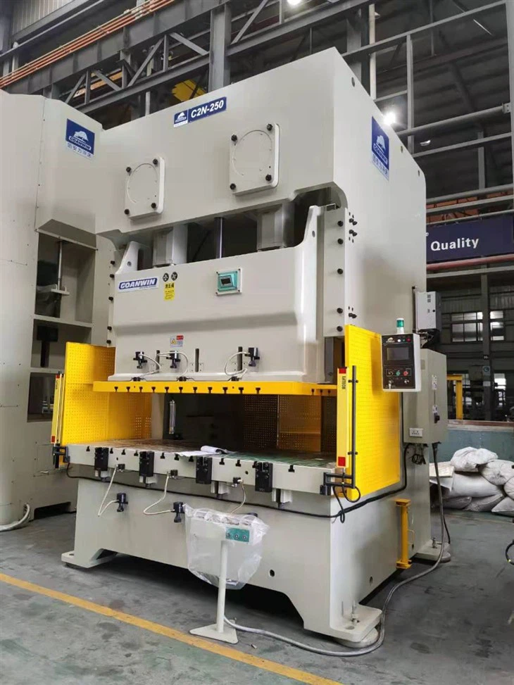

Next up, frame rigidity— this is the bread and butter of Gap frame presses. The whole “C” shape means the frame opens slightly when you apply tonnage, right? That’s called “frame deflection,” and even a good frame will deflect a tiny bit under full load. But if your frame is made from thin steel or was poorly machined, that deflection is way higher, and it’s inconsistent because it depends on where the tooling is placed. For example, if you run a part with the tooling set all the way to the front of the frame, the deflection is more than if you set it in the center, so parts from the front of the press will be slightly different than parts from the center. That’s why deep throat presses (see here: C-Frame Deep Throat Press) are engineered to minimize this uneven deflection—they have extra bracing along the throat to keep the frame rigid even when tooling is extended. If your current press is showing uneven part sizes from side to side or front to back, frame rigidity is the first thing I’d check, not the tooling (I see shops waste hours swapping tooling only to realize the press is the problem).
Now, let’s talk about the parts of the press that move the ram— the drive system and ram guidance. The ram is the part that pushes the tooling down, so if it’s not moving straight up and down, your parts will be off. On older mechanical presses, ram guides can wear out, leaving side play so the ram shifts left or right as it moves. That side play changes where the tooling hits the blank, leading to slanted holes or uneven bends. Newer presses have linear ram guides, which are way more accurate, but they need regular lubrication—skip the weekly lube check, and you’ll get friction that makes the ram move inconsistently. Also, something I see a lot: off-balance loads. If you set a heavy part on one side of the tooling, the ram shifts under the weight, and even if it’s a tiny shift, it messes up the part. The fix is to always center the tooling and the blank in the press’s load path—no exceptions.
Wait, I should mention mechanical presses vs other types here because a lot of people don’t realize the difference. Our C-frame mechanical presses (here: C-Frame Mechanical Press) use a flywheel and clutch to transfer energy, which is super consistent for high-volume runs, but if the clutch is slipping, that’s a huge accuracy killer. If the clutch doesn’t engage fully every cycle, the ram might stop 0.002 inches higher or lower than the last run, leading to parts that are underformed (if it stops high) or over-stamped (if it stops low). On the flip side, hydraulic presses use fluid, so their force is adjustable, but they have more deflection under load, which is why mechanicals are better for tight tolerances. But even the best mechanical press can’t overcome a worn clutch or incorrect clutch adjustment—check your clutch air pressure (if you have an air clutch) monthly, and adjust it to the manufacturer’s specs, not what feels right.
Tooling is obvious, but I still see shops writing off accuracy issues as “tooling wear” when they’re actually related to the press. But let’s be real: dull or misaligned tooling will ruin parts, no matter how good your press is. If your punches are chipped, or your dies are worn in certain spots, the part will thin unevenly or have burrs that throw off dimensions. But even brand-new tooling can cause issues if it’s not aligned with the press’s ram. If the tooling isn’t perfectly parallel to the bed of the press, every time you stamp a part, it’s being pressed at an angle, leading to tilted sides or off-center features. That’s a quick fix—most shops use a dial indicator to check parallelism, but I’d bet 30% of the stamping shops I’ve visited don’t do that regularly. Also, blank size and material consistency: if you use blanks that are slightly different thicknesses, the stamping force varies, so the final part dimensions change. Same with material hardness—if you switch to a batch of steel that’s harder than the last, you might need to adjust the press tonnage to keep the part accurate. A lot of shops skip testing material batches, and that’s a common hidden factor.
Cycle speed is another one people don’t talk about. When you’re running high volume, it’s tempting to crank up the press speed to get more parts per hour, but going too fast hurts accuracy. Why? Because at higher speeds, the ram has less time to fully engage the tooling and form the part evenly. Also, the flywheel on mechanical presses takes a split second to reach full speed—if you start stamping before it’s up to speed, the force is inconsistent. I usually recommend running at 80% of the press’s maximum speed for high-tolerance jobs. If you need faster cycle times, get a higher-speed press, don’t push your current one beyond its sweet spot.
Thermal expansion might seem random, but it’s a real issue, especially with metal parts. When a press runs all day, the frame, ram, and tooling heat up slightly—metal expands when it’s warm, so the distance between the ram and bed changes, leading to parts that are slightly thicker or thinner than they were in the morning. For example, if you’re stamping a part that needs a specific inside diameter, a 0.005 inch expansion of the ram could make that ID too small. The fix? Run a few test parts for 10 minutes before your production run to let the press stabilize, then adjust your die height to compensate for the slight expansion. A lot of shops start production right away and wonder why the first 50 parts are different from the last 500, and thermal expansion is usually the culprit.
Last but not least, operator error. I know, it sounds basic, but it’s way more common than you’d think. Things like not loading the blank squarely into the die, not checking die height between runs, or ignoring small warning signs like weird noises from the press. I had a client last year who was getting 10% of parts with misaligned holes, and it turned out the operator was flipping the blank wrong every 50 parts. Another shop was skipping die height checks because it took “too long,” and after a week, the die had shifted 0.003 inches, ruining an entire batch of parts. Training your operator to spot small issues and stick to a regular checklist (lube, check ram alignment, confirm tooling placement) goes a long way in keeping parts accurate.
At the end of the day, accuracy in stamped parts is a team effort between the press, tooling, material, and operator. If you’re dealing with consistent accuracy issues, start by asking yourself: did I pick the right C-frame press for my part? Have I done regular maintenance on the crank, ram guides, and clutch? Is my tooling aligned and in good shape? These are the basics that skip all the fancy jargon. If you’re in the market for a press that’s built for tight tolerances—whether you need a single crank for small runs, double crank for high precision, deep throat for large parts, or a reliable mechanical press for volume—we can help you find the right fit. Stop guessing why your parts are off, and let’s work through your setup to get the accuracy you need for your runs.
REFERENCES
- Metal Stamping Technology Association. (2021). Factors Governing Part Accuracy in Mechanical Press Operations. Stamping Industry Journal, 45(2), 112-127.
- Smith, J. D. (2019). Frame Deflection in Gap Frame Crank Presses: Measurement and Mitigation. International Journal of Manufacturing Technology, 101(3), 897-908.
- Press Maintenance Association. (2022). Preventive Maintenance Checklist for Mechanical Stamping Presses. Industrial Maintenance Digest, 18(4), 42-48.
- Lee, S., & Park, H. (2020). Thermal Effects on Ram Alignment and Part Accuracy in High-Volume Stamping. Journal of Precision Engineering, 24(1), 56-63.


